Friday, January 18, 2019

How To View Layer Sets Quickly - Altium

Each layout software is slightly different in how you view sets of layers during the routing process. If you made the transition from Orcad PCB Editor to Altium like I did, then you're familiar with what were called 'Views.'

These views are a way to group layers for quickly jumping back and forth between layer sets. Altium has a similar thing which it calls 'Layer Sets.' For those familiar with Orcad PCB Editor, the video below should seem normal.

The next video shows how to define layer sets for quickly switching between groups of available layers.

The key to quickly viewing groups of layers is to put these layer sets on hotkeys so that you can quickly swap during routing. What I do in the video below is click on the Manager Layer Sets menu 'LS' and then Ctrl-Click on the Top Layer layer set. This brings up the Edit Command window for assigning a hotkey such as one of the Num Pad numbers. I usually start with Num1 for Top Layer, Num2 for Bottom Layer, etc.
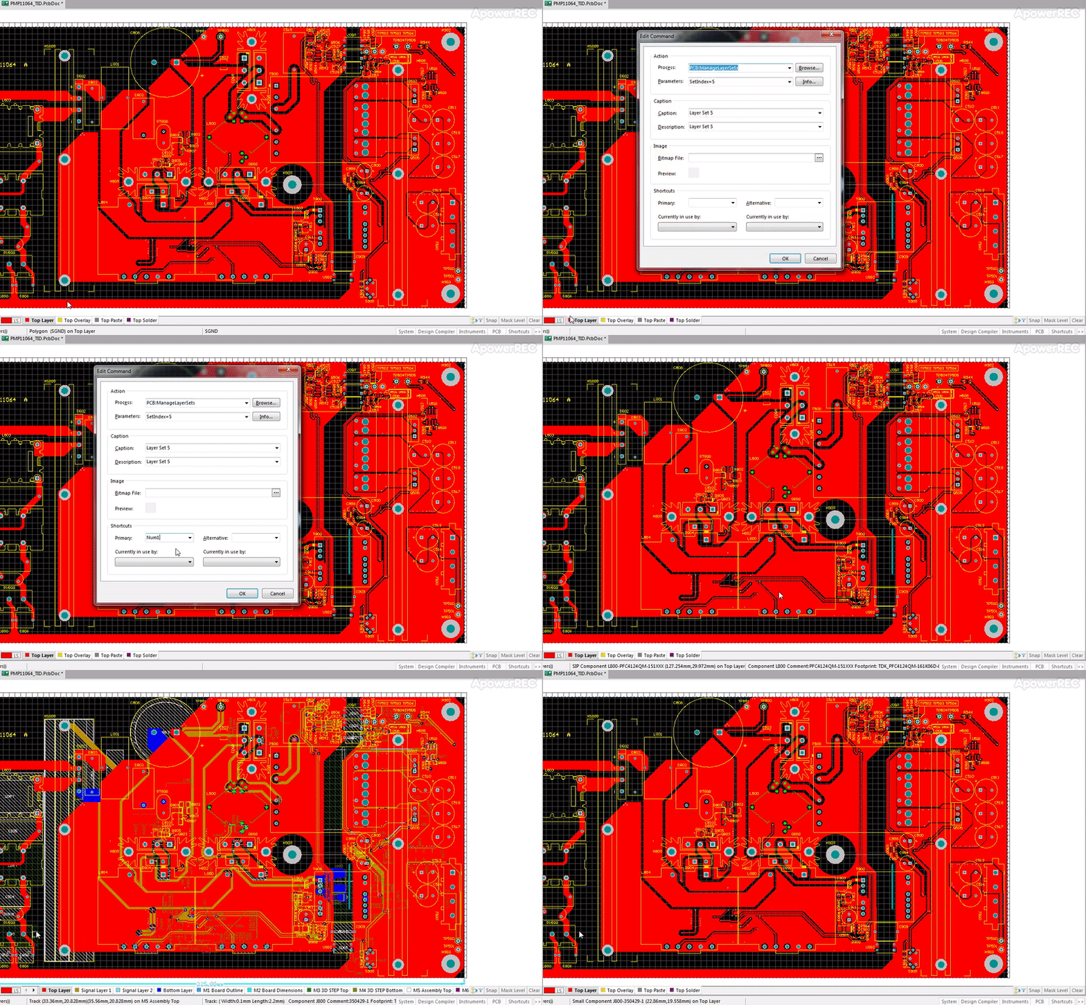

Now that you've got layer sets defined in Altium and you know how to assign hotkeys to them, you'll be able to quickly switch between groups of layers. This concept is extremely useful in reducing the amount of clutter on the screen, and it allows you to have go to layer sets for views such as Assembly Drawings, Top and Bottom Views, Component Outlines, Etc.

I hope you find this useful. Comment below on how you use layer sets and let me know if you have Altium questions I can help with.

Saturday, January 12, 2019

Using Component Classes in Altium with Rooms

When doing layouts in Altium, it is useful to bundle components into Component Classes for organizing into rooms and applying design rules. To do this, I highlight the all the components in the schematic that I want to group (making sure to enable Tools -> Cross Select Mode).

Once this is done, I go to the PCB document where the components have already been imported and I arrange them into a rectangle on part of the PCB (Tools -> Component Placement -> Arrange Within Rectangle). You should get something like the picture below.


Now that you can see all the components you're interested in, you want to draw a Room around the group of components (Design -> Rooms -> Place Rectangular Room). You can press tab and get the dialog shown below. Once you have this dialog up, you can change the name of the room. Here I typed in EthernetRoom and then pressed Ok.

If we double click on the room just created, we'll see 'Component Class 2' was created and all the components we drew in the room selection have been added as members. You can check the defined classes to verify (see below). I'm going to rename this to EthernetClass and then edit the room definition by double clicking on the room rectangle.


Here I'm editing the drop down boxes so that EthernetRoom contains objects that match everything in the EthernetClass Component Class.


Now we've got a room with assigned components in it that can be used for easier component placement. Dragging this room around will move components as well as visible polygons, traces, etc. In addition to placement, rules can be assigned in the Design Rules to Component Classes. Rooms can also be used for Channel designs that have the same schematic and layout repeated multiple times.


Hope you found this one useful and interesting. If you have questions, or other topics in Altium you need help with, comment below and I'll be more than happy to help.